 Français
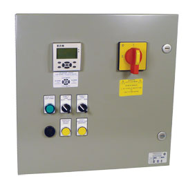
PL25P
Dual Pump Control Panel with 5 floats
Control system for automatic fuel tank fill with two pumps and five floats. The pumps work alternately and the floats and pumps are both monitored for defective operation.
BENEFITS
- Maximum security monitoring
- Detects fuel leak
- High reliability components
- Economic
- Easy to install
FEATURES
- CEMA 12 steel , 24’’x24’’x8’’ enclosure
- 24 Vdc power supply
- (2) Motor starter with protection breaker
- Disconnect without fuse
- Breaker on control side
- PLC Moeller with 6x3 cm display
- Logic module with 20 in/10 out
- (2) Auto-Off-Manual Selector
- Acknowledge button
- Audible alarm
- Bypass button for very low level alarm (initial)
- LED lamp for "Auto Mode Functional" state
- Terminal block
- Electrical & physical drawings
- Bill of materials
OPERATION
FLOAT LEVEL FUNCTIONS- FL1: High level alarm, pumps stopped
- FL2: Pumps stop in automatic mode
- FL3: One pump start in automatic mode
- FL4: Low level alarm, pump running stops and pump in standby starts
- FL5: Very low level alarm (flood), pump stops and generator stops.
Option: Open contacts in low level (specify).
SYSTEM ACTIVATION Select one of two pumps in manual mode. A push-button allows the pump to operate up to level float 5. Once this level is reached, setting to automatic mode is now possible and one of the pumps will operate up to level float 2.
MANUAL OPERATION A selection AUTO-OFF-MAN is supplied for each pump. In manual mode, the selected pump will stop if the high or the very low level is reached or if there is a leak in the reservoir.
AUTOMATIC OPERATION Normal operation:
Pump starts once the fuel level reaches the float 3.
Operating pump stops once level reaches the float 2.
The pumps will operate alternately under each start command and will transfer if one of the pumps fails.
Functions of alarms in automatic mode: The following messages will appear on the screen in case of the following failures:
- High level (FL1): Pumps stop
- Low level (FL4): Operating pump stops, standby pump starts
- Very low level (FL5): Both, the pumps and the diesel motor stop
- Failure pump 1 or 2: If there is no flow in a pump 30 seconds after the start command, a ‘Pump failure’ alarm is transmitted and the standby pump is started. Under overload conditions, a ‘Pump failure’ alarm is transmitted and the standby pump is started.
- Main tank leak
- Day tank leak:
- Level 1 pre-alarm
- Level 2 alarm & pump stop
- High level
- Low level
- Very low level
- Pump P1 failure
- Pump P2 failure
- Selector not in Auto mode, P1 or P2
- Open circuit breaker 52-1 or 52-2
- No AC supply (by remote indication only)
- Failure of floats 2, 3 or 4.
A sound alarm and a silence push-button are provided.
- Pump P1 and/or P2 running
- Pump P1 and/or P2 stop
- Pump P1 and/or P2 defective
- Each Float status
- A green light on the panel will indicate ‘’Auto Mode Functional’’.
| PL25P |
| Documents | English | French | Spanish |
|---|---|---|---|
| Brochures | p_pl25p_eng | p_pl25p_fra | |
| Presentations | |||
| Installation | |||
| Manuals | |||
| Technicals Informations |
© Enertec Electrical Controls (1989) Inc., 2024. All rights reserved.